Saturday, March 24, 2012

IFTLE 94 Experts Discuss Interposer Infrastrucrure at IMAPS Device Packaging Conference

IFTLE brought together a  panel of manufacturers, users and market specialists at the 2012 IMAPS Device Packaging Conference in Fort McDowell AZ to discuss the Evolving 2.5D / 3D Infrastructure. [ Douglas Yu, Sr Director of front end and back end technology development for TSMC; Jonathon Greenwood, Director of Packaging R and D at GlobalFoundries;  Remi Yu, Deputy Division Director of UMC]memory suppliers [Nick Kim, VP of future electronic packaging technologies at Hynix] assembly houses [ Rich Rice, Sr VP of sales for ASE and Ron Huemoeller, VP of Advanced 3D interconnect at Amkor] users [Matt Nowak, Sr Director of Engineering at Qualcomm] and Market specialists [ Jan Vardaman, President of TechSearch Inc].

(Click on any of the images below to enlarge them)

       [l to r] Doug Yu [TSMC], Garrou [IFTLE],Huemoeller [Amkor], Vardaman [TechSearch],
Greenwood [GlobalFoundries], Yu [UMC], Kim [Hynix], Nowak [Qualcomm], Rice [ASE]


When asked whether 2.5/ 3D TSV technology has been narrowed down to copper TSV middle from IDM or foundries and some vias last backside all the panelists agreed with this conclusion. When asked about standard TSV dimensions, the foundry and OSAT representatives all agreed that 5-8 µm  on 50 µm thick Si looks like it has become the standardized offering that many of their customers are expressing interest in. When it came to interposers, they similarly all gave the nod to 100 µm thick interposers with ~ 10 um diameter TSV. 
Sourcing Interposers
A significant portion of the panels time was spent discussing current and future interposer sourcing. Assuming the attributes of “fine”vs “coarse” interposers as defined in the table below, the question becomes “where will these interposers be coming from” and “what will they be used for” ? 

So far announcements from Xilinx and Semtech indicate that they will both be using “fine pitch” interposers i.e fabricated by ~65 nm dual damascene [DD] CMOS processing by TSMC and IBM respectively. Altera and Nvida have also announced similar high density interposers for future use as have other graphics chip makers.
While all the OSATs have RDL technology capable of fabricating “coarse” interposers so far none of the major players [ ASE, Amkor, SCP, SPIL] have announced that they are entering the interposer business.

While all of the current roadmaps point to 2012-2014 as being the date for initiation of mass production for 2.5/3D products one must now ask where is the interposer production to meet this demand. If these lines are not in place now, is it easonable to think that products using them be qualified and in mass production within the next 24 months ?
During his conference presentation Amkors Huemoeller indicated that they would not be manufacturing interposers and their search of the industry for sources  indicated that only 3 players were close to being ready to deliver interposers that wee useful to Amkor, namely TSMC, UMC and GlobalFoundries.
 While glass panels and even possibly advanced laminates presented interesting possibilities for low cost future products, Amkor’s perspective is that  they are in the earliest stages of R&D.
All 3 of the foundry panelists indicated that they will be commercializing fine featured interposers although as we stated only TSMC and IBM had announced small volume product production has been initiated.
When asked about rumors circulating that OSATS are looking to put equipment in place to manufacture DD “fine pitch“ interposers, both Amkor and ASE indicated that they had no plans to do so.
IFTLE concludes that despite significant “industry chatter” the only programs that can afford interposers, so far, are programs that require the density or other attributes provided by fine featured interposers which can only be provided today by foundries /3D active IDMs. While we can anticipate that there might be products in the future that can be designed to take advantage of “coarse” interposers, and some of the initial fine interposer activities such as memory + logic + graphics chip applications might be able to migrate to coarse interposers as they become available, we will, initially at least, be limited by the availability and cost of foundry supplied interposers. 
The Evolving Infrastructure
TSMC reconfirmed  that they will provide full 2.5 / 3D service including chip design and fabrication, stacking and packaging [ see “2.5D announcements at the Global Interposer Techconferenceand “TSMC repeats call for foundry-centric 2.5/3D industry” ]
TSMCs Yu indicated that they have made their thoughts clear in the past few months and it can be found clearly delineated on their web page. During his plenary lecture Yu once again indicated that fabrication of chips on interposers was not as easy as making prototypes makes it look and they strongly favored controlling and being responsible for the full process.
When asked about supplying memory needs, Yu indicated that they would also handle that by having partnerships in place to supply the required memory although these partners were not identified.
When asked for their positions, UMC and Global Foundries indicated a preference to work under the open ecosystem model where chips from various vendors could be stacked and assembled by OSAT partners.
When asked how the current economic issues surrounding Elpida was affecting the UMC/Elpida/PTI partnership, UMCs Remi Yu responded that this was only one engagement that they had in place for 2.5/3D and that they were moving forward with others.
Amkor’s Huemoeller indicated that foundries would be supplying interposers and they [ the OSATS] would be assembling them.
 ASE agreed short term but indicated that longer term they envisioned a broad “pie” with space for several types of players. ASE envisions future applications where coarse interposers would find their niche and be an important part of the technology base
Both of the OSATS, as would be expected, favored the open ecosystem model where chips from various suppliers would be assembled at the OSATS. 
Qualcomm reiterated a position that they have expressed in the past which is that interposers would add substantial cost to 3D stacking and as such probably would not be a broadly accepted solution for low cost mobile products
TSMCs Yu responded that indeed the addition of an interposer added cost to  the overall component, but that “...this [2.5D] solution also offers cost savings by reuse of IP and separating digital and analog circuitry and allowing partitioning of costly SoC “ and that this in fact could make it the lowest cost solution..
When Hynix was asked whether they would be offering memory stacks containing TSV as have been already announced by Samsung, Micron and Elpida Hynix Kim responded that he expects “2 and 4 chip memory stacks with TSV to be in mass production in 2013”
When the panel was asked with the wide IO memory standard is now in place. what other standards were needed quickly Nowak of Qualcomm indicated that the upcoming Semi handling and transport standards were needed and noted that standardization was also needed in the ESD area and  standardization in the “design exchange formats” where he feels Si2 is taking the lead.
When asked for their opinion on the current status of design tools all 3 of the foundries indicated that current design tools are adequate to move forward. Qualcomm’s Nowak offered that logic on logic design tools were still lacking.
In terms of test strategies UMC would like to see some better standardization in the test area while Yu of TSMC drew a chuckle from the crowd when he noted that test needed to be minimized. Similarly, on the assembly front Rice indicated that ASE is having to test “everything” till the yields are up and Amkor quickly concurred.
Focusing on the first generation of 2.5/3D  stacking interconnect all accepted that this will be done with Cu/Sn eutectic by reflow or thermo-compression bonding.   When asked what was limiting direct Cu-Cu bonding all agreed that copper bonding was not ready for prime time just yet. Yu a strong proponent of copper interconnect, noted that current copper bonding options have yield issues that have not yet been overcome “current requirements for pads are too large and the required CMP of the interfaces is causing dishing that must be handled...HVM of copper –copper bonding options is tougher than showing research samples”
When similarly asked about  hybrid metal/oxide bonding schemes where oxide / copper surfaces are polished flat, oxide bonded then subsequently oven annealed to strengthen oxide bond and form Cu-Cu bonds (as shown by Ziptronix and Leti) no panel members were willing to say that this technology was close to commercialization.  TSMC responded that these technologies required very flat surfaces which were difficult to obtain due to dishing and other issues and that in general such technologies were “not ready right now”.  ASE expanded that this option was not required to solve todays problems and therefore was being looked at as a interesting R and D solution which could find its niche later. During Q and A Cook of Ziptronix offered that she thought their technology was ready and simply awaiting the commitment of a significant player. When the panel questioned copper migration issues due to miss alignment of the Cu-Cu bonds, Cook offered that their process which encapsulates the copper pillars in nitride barrier. 
Rumors abound that TSMC is designing the apple A6 processor for ipad and iphone with 3D TSV. When asked to comment on this or whether Samsung was also offering TSV in their design of the A6 this question brought the expected “no comment” from TSMCs Yu and silence from the rest of the panel. Similarly no one would offer up comment about who would be supplying Sony who announced that they would require TSV interposers for their next Playstation upgrade.
When asked about timing for the expected HVM of wide IO memory stacks for tablets, Qualcomm responded probably 2013 and Hynix responded maybe 2015.

For all the latest in 3DIC and advanced packaging stay linked to IFTLE................

Saturday, March 17, 2012

IFTLE 93 2.5 / 3D at the 2012 IEEE ISSCC

There were several interesting 2.5 / 3D presentations at the recent IEEE ISSCC conference.

2.5D Integrated Voltage Regulator Using Magnetic Core Inductors on Silicon Interposer
Minimizing energy consumption is a performance goal of all of today’s devices including  microprocessors. Dynamic voltage and frequency scaling (DVFS) is a technique for performing “on-the-fly” energy-use optimization. Implementation of DVFS requires voltage regulators that can provide independent power supplies and can transition power supply levels on nanosecond timescales, which is not possible with modern board-level voltage regulator modules (VRMs).

Switched-inductor integrated voltage regulators (IVRs) can enable effective implementation of DVFS, but the primary obstacle facing development of IVRs is integration of power inductors. This work by Columbia University and IBM presents “an early prototype switched-inductor IVR using 2.5D chip stacking for inductor integration” by  combining magnetic materials, chip-stacking design and a 2.5D chip packaging process. The power converters integrated onto the same chip, or into the same package, as microprocessors "significantly improves computational performance per watt of power consumed

They report that the technology can reduce power consumption, by 10-20% in a typical US data center
Inductors are fabricated on the silicon interposer in an elongated spiral with a Ni-Fe magnetic core encasing the copper windings on the long axis.  “The Ni-Fe is deposited under a magnetic biasing field so that the hard axis of magnetization forms along the width of the core as shown in the figure. Inverse coupling between adjacent inductors, is utilized to avoid magnetic saturation of the core.” The inductor fabrication involves successive electroplating deposition of the bottom magnetic core, copper windings, and top magnetic core. The windings are electrically isolated from the bottom magnetic core with a layer of silicon nitride, and from the top core with ”hard baked photoresist”.

(Click on any of the images below to enlarge them.)


IBM Stacked Memory on Processor
There have been rumors out there that IBM would be applying with their 3D technology in their upcoming Power7 devices. Their presentation at ISSCC may be the first look that we are getting at their early designs for processors stacked with cache memory using TSV technology.

This work describes a prototype 3D system, constructed by stacking a eDRAM memory layer and logic blocks from the IBM Power7TM processor L3 cache, and a “processor proxy” layer in 45nm CMOS technology enhanced to include TSVs. The 3D stack is constructed using 50 µm pitch C4’s joining the front side of the thick processor chip to TSV connections on the back side of a thinned memory. The TSVs are Cu-filled vias that are ~20µm dia and <100 µm deep.
Standard design methodologies with some 3D extensions were used to design each stratum. TSV locations for power and clock were pre-defined to match a regular grid. Some sites were de-populated to accommodate the eDRAM blocks.


Tezzaron Technology Used for 2 Processors

Old friend Bob Patti at Tezzaron was involved helping fabricate two of the processor modules shown at this years ISSCC

Georgia Techs  3D-MAPS: 3D massively parallel processor with stacked memory
3D-MAPS (3D Massively Parallel Processor with Stacked Memory) is a two-tier 3D IC, where the logic die consists of 64 general-purpose processor cores running at 277MHz, and the memory die contains 256KB SRAM (see Fig. 10.6.1). Fabrication is done using 130nm GlobalFoundries device technology and Tezzaron TSV and bonding technology. Packaging is done by Amkor. This processor contains 33M transistors, 50K TSVs, and 50K face-to-face connections in 5 x 5mm2 footprint. The chip runs at 1.5V and consumes up to 4W, resulting in 16W/cm2 power density


Tezzaron 3D technology was used to stack two logic dies using face-to-face (F2F) bonding, where the top die is thinned to 12µm and the bottom die is 765µm thick.  These F2F pads are used for signal and P/G connections between the two dies. The diameter of a F2F bonding pad is 3.4µm, and their pitch is 5µm. 3D-MAPS uses 235 I/O cells that are placed along the periphery of the core die. Each I/O cell contains 204 redundant TSVs, where each TSV connects between a metal 1 landing pad and a backside metal landing pad deposited on the backside of the silicon substrate. Each backside metal landing pad (56 x 56µm2) is wire bonded to the packaging substrate. The diameter, height, and pitch of a TSV are 1.2µm, 6µm, and 5µm, respectively

University of Michigan Centip3De

David Fick of the University of Michigan showed Centip3De another processor fabbed by Tezzaron. A 3-D IC stack using 128 ARM Cortex M3 cores and 256 Mbytes of stacked DRAM operating at near threshold voltage. The module has an un-thinned cache layer and a thinned core layer with WB connecting to TSV on the backside.


Hynix Dealing with Process Variation in a 3D Memory Stack
In general, commercial DRAM shows large process variation from chip to chip, which causes address access time variation (tAC).  In order to reduce the tAC variation, most high speed SDRAMs adopt a delay-locked loop (DLL) at the cost of additional area and power consumption.   
Hynix in their paper entitled “A 283.2µW 800Mb/s/pin DLL-Based Data Self-Aligner for Through-Silicon Via (TSV) Interface explains that this can be an even larger problem for stacked memory die. “For TSV-based stacked dies, large tAC variation results in higher power consumption due to short circuit current from data conflicts among shared IOs”. Since the number of IO  might be 512 or more for wide IO DRAM,  the additional power consumption can be very high. While it is desirable in mobile DRAM to exclude the DLL because of the power cost , TSV stacked DRAM for high-speed operation partially adopts a DLL in the master die (driver circuitry) . The DLL-based data self-aligner (DBDA) described by Hynix  reportedly reduces the data conflict time among stacked dies, consuming 283.2µW during read operation at 800Mb/s/pin. It dissipates 4.98µW in self-refresh mode with the help of leakage-current-reduction controller.

For all the latest in 3DIC and advanced packaging stay linked to IFTLE..............

Saturday, March 10, 2012

IFTLE 92 Advanced IC Packaging at InterNepcon Japan, Loss of a Dear Friend

At the recent InterNepcon Japan Exposition held at the Tokyo "big site" their "IC Packaging Technology Expo" contained some new information and some retreads that we have seen on IFTLE previously. Below I'll cover a few new items that may be of interest to you.

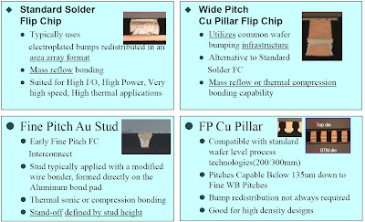
TI's Mark Gerber, a key player in bringing up their Cu pillar technology at Amkor addressed 3D packaging technology for next generation devices. Mark broke out current FC interconnect technologies into the following 4 categories indicating that fine pitch gold stud bumping was confined mainly to Japan.

(Click on any of the images below to enlarge them)


Sung-Il Cho of Samsung's test and package center looked at Samsung's Packaging Roadmap. He offered the following categorization for their DRAM, Flash and system LSI chips...


...and the following roadmap for flash technology development for solid state drives. Consistent with their corporate policy of holding new technology information "close to the vest" their inputs on 3D packaging with TSV were either ITRS roadmap slides or Yole roadmaps that have been published on these IFTLE pages before.


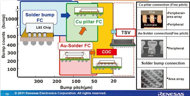
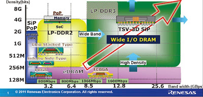
Keiichirou Kata of Renesas Advanced Package Development Dept. addresses their packaging roadmaps. He sees the major developing areas as FC BGAs, WLP and what he calls 3D Jisso (3D IC integration). Their FC technology roadmap is driven by desire for tighter pitches.


28 nm node chips will see a move to 108 um pitch and copper pillar bumps by the end of 2012.


Their proposed fan out WLP is an RDL first technology which they contend eliminates the issues of chip movement due to mold compound shrinkage.


They are moving to wide IO DRAM standards for low power DDR3 and beyond.


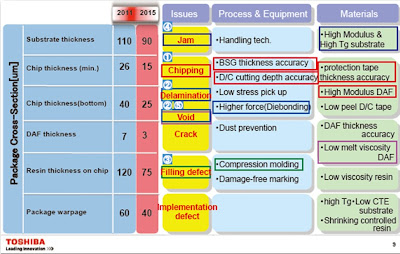
Ryoji Matsushima from Toshiba's Memory Packaging Engineering Dept. discussed equipment materials and processing issues for thin memory packages. High memory capacity, high memory access speed and thinner packages all point towards memory stacking with TSV.


Technical issues with thin packages are shown on the slide below.


In Memorium: Jackki Morris Joyner


This past week I was attending the IMAPS Device Packaging Conference in Ft McDowell AZ (coverage coming in a few weeks). Those of you who are long time readers of IFTLE know I am there every year and strongly support this IMAPS conference. In the end, what separates societies is people not content. Part of what makes IMAPS great to work with has been Jackki Morris, or as we knew her post marriage Jackie Morris Joyner. When she first told us of the impending marriage and that she was becoming Jackki Joyner we all teased her asking her to run around the buildng for us ( for our non US friends this is the name of a famous US Olympic runner) and she laughed along with us. Jackki was the kind of person who made your life better for having talked to her on the phone or corresponded by email. Everyone asks "how's it going" but she meant it. She genuinely cared about people... you just could tell.

The last time I talked with Jackki she was working the IMAPS table with her husband Cliff Monday night. When she saw me she gave me a hug and she turned on her computer and showed me pictures I had sent her of my grandaughters a few years ago. She had pages and pages of pictures of all the friends she had made through IMAPS because she just was that way. We shared funny stories of past conferences and laughed before I let her get back to work.

The next morning she was noticeably missing and Exec Dir Michael O'Donoghue revealed to several of us that Jackki had become quite ill during the night. By the time she made the hospital her heart had stopped several times and she was in intensive care with Cliff by her side. This cast a pall over the rest of the meeting and she remained in intensive are as we all left the meeting to go home. By the time I arrived home Friday she had passed away. The world is truly worse off today because this caring, loving person is gone.

Our prayers are with Cliff and her family

Anybody here seen my old friend Jackki
Can you tell me where she's gone
She cared and shared with a lot of people
But it seems the good they die young
I just turned around and she's gone

Sunday, March 4, 2012

IFTLE 91 IEEE 3DIC Japan 2012 part 2

Continuing to examine presentations from the 3rd Int IEEE 3DIC Conf held in Japan in Feb 2012.

Copper Protrusion

In the last several years PFTLE and IFTLE have brought copper protrusion to the forefront as an issue [see "Researchers Strive for Copper TSV Reliability" Semi Int, 12/03/2009] and reported on technical solutions as they appeared from IMEC [see IFTLE 6 "Cu-Cu and IMC Bonding Studies at 2010 ECTC..."]; TSMC [see IFTLE 34, "3DIC at the 2010 IEDM"] and others. IME has now reported on their study of 5 um x 50 um Cu TSV as they were annealed from 250 to 450C.

Cu expands vertically because it is constrained by the surrounding silicon substrate. Because it expands plastically it does not return to its original length when the sample is cooled down.

(Click on any of the images below to view the full-size version)


The effects of anneal temp, anneal time, via diameter and via depth are shown below where "room temp" refers to the protrusion present after anneal and return to room temperature and high temp refers to protrusion after anneal while still at the elevated temperature. As with previous studies they found that CMP after anneal retards any further protrusion if the temperature is again elevated.


Bottom line is that protrusion is minimized by small diameter, low aspect ratio TSV.

Samsung System LSI Division has also looked at the Cu protrusion issue and report similar results i.e that Cu protrusion can be reduced by heat treatment before CMP and that Cu protrusion and delamination strongly depend on TSV dimensions.

When the via diameter was in zone A all the vias showed high Cu extrusion and via delamination, but TSV diameters from zone B showed no problems.


Micro-cracking caused by Lateral Extrusion

Conference Chair Koyanagi and co-workers at Tohoku Univ also examined TSV dimensions and the effect of high temp annealing. An array of Cu TSV with diameters ranging from 3 to 30 um at three different pitches were annealed from 200 to 400C. Both the lateral and vertical protrusion of the copper was monitored.

Again larger diameter TSV (at a constant depth) show higher extrusion, but also that lateral extrusion (extrusion in the x-y after Cu has protruded from the surface) increased with anneal temp. For example 5 um TSV on a 10 um pitch extrude laterally 2 um at 400C. This would put them within 1 um of touching! Stresses induced by the TSV also result in microcracking "...on the periphery of the TSV array and in between the TSV." Careful choice of TSV size and pitch is recommended.


Cu-Cu Direct Bonding

Copper-copper direct bonding continues to be a popular topic due to the promise of fine pitch, low resistance interconnect which are more mechanically reliable than IMC bonding (Cu-Sn-Cu) and should show less electromigration issues. Such processes are currently limited by the required bonding time / temperature which are usually reported as 30 min / 350-400C. The holy grail appears to be a thin die Cu-Cu thermo compression bonding process which requires low bonding temp and pressure.

IMEC and TSMC have studied the direct Cu-Cu bonding of 5 x 40 um TSV with (3) different configurations ; (1) no nail head exposed (Cu CMP'd flat with the oxide surface; (2) flat nail head (cu CMP'd flat and then oxide recessed and (3) natural nail head (stop grind short of the nail head, pull back oxide revealing "dome" shaped copper protrusion. The matching landing pad is a Cu surface CMP'd flat with the oxide surface. After bonding they observed that the "no nail head exposed" and the "flat nail head" sample s delaminated even when the bonding temp and or the pressure was increased. They assumed failure was due to the low % area that is actually used to bond (less than 1%). So, what is good for the design (less than 1% of the area occupied by TSV) is not good for the strength of bonding. The dome bonding was better due to its ability to deform. IFTLE interprets this as an ability of the domed structured to deform allowing shorter TSV to now touch their pads and bond. IFTLE also thinks this is a good reason to look at hybrid bonding schemes such as proposed by Ziptronix [see PFTLE 48, "Opening the Kimono, Ziptronix gives details on DBI Process"] and CEA Leti [see PFTLE 103, "Show me the Copper"]

Stacking of Ultrathin Die

Standard 3DIC thickness has focused around 50 um for the last few years. IMEC has now shared their results of ultrathin (25 um) die stacking.

After temporary bonding and grinding, oxide is pulled back for Cu TSV reveal. The revealed "nail heads" are passivated with 3 um BCB and reconfigured with Cu/BCB RDL. Cu/Sn bumps are then fabricated on the landing pads. The 25um thick die are diced while still bonded to the carrier. They note that "this is required to have enough mechanical support during stacking"

Both NUF and WUF were looked at for underfill solutions. NUF is unfilled polymer dispensed onto the landing die prior to bonding and WUF is filled underfill film laminated to the thinned wafer while still on the carrier.


Issues with NUF were: (1) underfill trapped between the bumps;(2) voids between top and bottom die and (3) induced topography due to underfill shrinkage on cure. Shrinkage of the underfill upon curing and the CTE difference between a microbump and the underfill cause a bending of the die over the ubump connection. For an unfilled underfill and a 25um thick die a 40% increase in the drain current was observed to occur.

After several failed tries, they decided to focus on WUF with 60% filler loading. WUF was vacuum laminated onto the die and gave much better topography and the use of a filled underfill resulted in reduced stress.

They also found that increase in the die thickness from 25 to 50 um resulted in a stress reduction of 3X. Final conclusions were that 50 um thickness die were currently much better option for scalable manufacturable process and that reduction in the TSV diameter from 5 to 3 um will reduce the required KOZ by 64%.

Wireless Product with Design Partitioning

ST Micro and CEA Leti described their program to partition the digital and analog functions of a HD video transmitter onto separate die and stack them using Cu TSV and ubumps.


TSV are 10 um with a 40 um pitch and wafers are 80 um thick. Cu pillar interconnect are 25 um dia and 30 um high. Reliability tests were done at package level using JEDEC level 3. No delamination and no electrical failures were obtained after 1000 cycles.

--------------The next IEEE 3DIC Conference will be held in the fall of 2013 in San Francisco--------------

Coming up in IFTLE :
-advanced packaging from InterNepcon Japan
-3D as the ISSCC
-detailed coverage on the IMAPS Device Packaging Conference and more

For all the latest in 3D IC and advanced packaging stay linked to IFTLE............................