Sunday, September 26, 2010

IFTLE 17 ITRS Assembly and Packaging Roadmap

As we said last week, the 2009 ITRS roadmap (released this summer) is the first roadmap where 3D IC has become an important and integral part of both the Interconnect and the Assembly and Packaging sections. It is certainly worth our time to look at what they have to say about 3D and other advanced packaging topics. The full reports can be accessed here (Interconnect; Assembly and Packaging). In IFTLE 16 we have examined the Interconnect roadmap .

Assembly and Packaging Roadmap
Organized in nine major sections:

• Difficult Challenges
• Single Chip Packaging
• Wafer Level Packaging
• System Level Integration in Package (SiP)
• 3D Integration
• Packaging for Specialized Functions
• Advanced Packaging Elements
• Environmental Issues
• Cross-Cut Issues

Singe Chip Packaging:

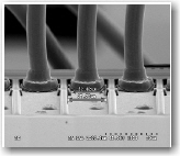
Fine pitch copper wirebond has been introduced into the mainstream industry. [ see PFTLE 86 “Adv Pkging From Rimini”, 07/12/2009 ] Replacement of Au wire by Cu is the last frontier for packaging materials cost saving. They note that advanced nodes and low k materials will demand finer diameter wires for Au as well as Cu (below the 18 um being practiced today). While copper wirebond has been in use for power devices with 50 micron diameter wires and low IO counts, fine pitch Cu wirebond is a more recent development. Using fine pitch Cu wire diameters of less than 25 µm requires improvements in understanding of wire properties, IMC formation, wire bonding processes and equipment development and control for wire oxidation. Pd coated wire has been introduced to eliminate the need to for forming gas in production. The WB figure shown here is of a 18 µm Cu wirebond in a PBGA.

Some of the technology issues being addressed are bonding overhang die (i.e in a WB 3D stack like PoP and PiP ) and wire bonding on both sides of the lead frame shown below.
Flip Chip

For flip chip pitch, lower than 150 µm, has been limited by availability of high-volume cost-effective substrates and high-volume defect-free underfill processes. Application for plated wafer bumping including copper pillar wafer bumping is being expanded beyond microprocessor applications.

For applications beyond the microprocessor, graphics and game processors, FC CSP packages have been developed for applications with smaller die, lower IO array pitch and low profile small package format requirements. Primary driver has been the mobile market application, and drop test is the important reliability requirement.

Molding for FC devices
A new approach presently under investigation is underfill molding (MUF) for flip chip in package solutions. While thin packages are prone to warpage, and chips with low-κ dielectrics are more sensitive to stress low modulus molding compounds are in development to minimize the problems.


Substrates
Package substrates are both the most expensive element of packages as well as the factor limiting package performance. Advances in package substrate technology will be required to meet the cost and performance projections of the Roadmap.

Handheld consumer devices are driving ever thinner substrates and finer patterns on laminate. Total thickness has been reduced to 100 µm based on 60 µm cores in high volume manufacturing. 50 µm cores and 35 µm prepregs are available but cost is still high and improvements in handling equipment are needed to take these materials to high volume. Below 35 um thickness, new high performance low cost material is required to meet the market needs.

As copper thickness shrinks in traces and plated through holes, these features become susceptible to thermal expansion in the z-direction. CTE in z-direction must be reduced to 20 ppm/degree for core materials. The typical approach is to add filler to the resin system which typically degrades other material properties or introduces process disadvantages.

Low Κ dielectric substrates for FC-BGA are needed for high-speed transmission Incremental materials improvements enable κ~3.4 today. Materials are available with κ down to 2.8 but are still far too expensive for broad market application. There is no cost effective solution available for κ~2.5 and below. For such low κ, new reinforcement materials need to be developed as well.

Wafer Level Packaging
Wafer level packaging (WLP)is being defined as a technology in which all of the IC packaging process steps are performed at the wafer level. The original WLP definition required that all package I/O terminals be continuously located within the chip outline (fan-in design) producing a chip size package. From a systems perspective, under this definition, the limitation on WLP was how many I/O could be placed under the chip and still have a board design that can be routed.

However, new packages have recently been introduced which are “Fan-out” WLP. They are processed by placing individual sawn die into a polymer matrix that has the same form factor as the original silicon wafer. These “Reconstituted” wafers are then processed through all of the same processes that are used for “real” silicon wafers, and sawn into separate packages. The die are spaced in the polymer matrix such that there is a perimeter of polymer surrounding each placed die. This area can be used during redistribution (RDL) to “fan out” the RDL to an area larger than the original die. This allows a standard WLP solder ball pitch to be used for die that are too small in area to allow this I/O pattern without ‘growing” the die to a larger size.

Thus WLP technology can now include traditional wafer level chip size packages (WLCSP), Fan-out wafer level packages, wafer level packages with TSV, wafer level packages with Integrated Passive Devices (IPD)s. This is shown in the figure below.
In contrast to flip chip assembly, WLP assembly typically does not require underfill. Solder balls with a diameter greater than 250 µm are typically used to increase package reliability. For applications where low package height is required, smaller solder balls can be used (smallest pitches used in the market are 0.4 mm in conjunction with under-fill which would be necessary to pass typical drop tests.


SiP
The roadmap now defines SiP as “...a combination of multiple active electronic components of different functionality, assembled in a single unit, which provides multiple functions associated with a system or sub-system. A SiP may optionally contain passives, MEMS, optical components, and other packages and devices”. These may be arranged horizontally, vertically or be embedded as shown below.

3D Integration


Not much here that we haven’t already covered extensively in PFTLE and IFTLE. Below is a nice graphic from Intel showing the evolution of memory on logic (without timelines).


There is extensive discussion on chip package co design which the roadmap concludes will be necessary to reduce time to market and cost. There are also discussions on the specific requirements for opto, Rf, MEMS, automotive and LED packaging – the latter certainly being a hot topic recently. [ see PFTLE 123 “LCDs Coming to a Lighting Application Near You”, 3/18/2010 ]

One complaint I have about this document (same as the interconnect document) is that there are far to few primary references contained in the document ( 20 total) Roadmaps like this should be well documented with primary sources.

For all the latest on 3D IC and advanced packaging stay linked to IFTLE.......

....... previous PFTLE blogs are located at www.pftle.net........

Monday, September 20, 2010

IFTLE 16 the 2009 ITRS Interconnect Roadmap - a Chance to Say “I Told You So”

The 2009 edition of the ITRS Roadmap didn’t become available till this summer. This is the first roadmap where 3D IC has become an important and integral part of both the Interconnect and the Assembly and Packaging sections. It is certainly worth our time to look at what they have to say about 3D and other related topics. The full reports can be accessed here (Interconnect; Assembly and Packaging).


The ITRS Interconnect Roadmap


Credit goes to the Interconnect committee for two reasons:
1) Unlike JEDEC [see PFTLE 128 “3D IC Standardization Begins” ]the committee list their members so you can tell exactly who was involved with generating the document. Bravo gentleman !
2) I have, in the past,been a harsh critic of the mistakes this committee made in the late 1990’s when some absurd predictions were made about where low K was going and by when [see PFTLE 44 “Upcoming 3D Integration events; Issues with the ITRS 3D Roadmap”,9/11/2008]. As you can see in the fig below, the projection the Low-K probably will not get below 2.5 with current material sets is a much more rational conclusion based on historical and current published data. This is important both to 3D and to advanced packaging of “low-K” chips. ( I say current materials new material options become available all the time for instance see "Low K Material Family Introduced by SBA Materials" 09/07/2010 SST)

Again, bravo for this open and frank discussion of past errors in projection (see figure below).

The interconnect roadmap now accepts that “reduction of the ILD к value is slowing down because of problems with manufacturability. The poor mechanical strength and adhesion properties of lower-к materials are obstructing their incorporation. Delamination and damage during CMP are major problems at early stages of development, but for mass production, the hardness and adhesion properties needed to sustain the stress imposed during assembly and packaging must also be achieved. The difficulties associated with the integration of highly porous ultra-low-κ (к ≤2) materials are becoming clearer…..the slowdown of low-к in this edition, is further reflected by delaying low-к progress by one year in light of the actual pace of deployment of new technologies.”
They also conclude that despite the fact that “…spin-on dielectrics have the benefit of less dependence on precursors than CVD, that is, one tool can handle a variety of materials, including porogen. Various spin-on low-κ materials including porous materials have been studied. However, PECVD-SiCOH has been the dominant low-κ ILD film. Non-porous spin–on materials have not been used except in some special cases. Spin-on polymer and spin-on MSQ with к ≥ 2.4 are unlikely to be used for actual logic/memory devices, consequently spin-on materials, except porous-MSQ, have been deleted from the potential solutions figure”.

Finally, a formal roadmap admission that spin-on-organic ILD has been a total failure. What was the holy grail of chemical companies in the late 1990’s, and led to career ends for several major players, is at last labeled, what some of us knew all along – a dismal failure. Those who worked with me in those years know that I was a strong opponent of spending money to develop such materials and paid a price for my failure to support certain materials. A stronger man might be able to resist saying “I told you so” …..too bad I’m not a stronger man.

……..and now onto 3D in the 2009 Interconnect Roadmap

3D Definitions and Naming


For any technology to catch on we must all be using the same language to describe it.


The 3D roadmap writers ( which I’m sure included Arkalgud, Beyne, Ramm, Pozder, Scannell and Smith among others) have chosen to go with the IMEC 3D definition set which is modeled after the JISSO hierarchy levels.


3D-P and 3D-WLP seem pretty straight forward and I can see little resistance developing about their use. 3D-P meaning stack and wire bond technology that is firmly entrenched at all the OSATS and 3D –WLP based on WLP techniques performed after chip fabrication. Basically your TSV last, vias backside technology used in production today for CMOS image sensors.


I do have some resistance to use the next two however, not because they are incorrect, but rather because they will conflict with the near decade of 3D papers already out there. They use 3D –SIC to mean the stacking and interconnecting of large and medium circuit blocks and 3D-IC to mean 3D layer connection at the local interconnect level. I think most of us have been using 3D-IC (also seen as 3D IC or 3DIC) to mean what will now be called 3D-SIC. IFTLE will begrudgingly try to conform to the new acronyms (apologizing in advance for when I will surely slip up)


Always of interest are the ITRS tables projecting what requirements will be needed at a given point in time for a given technology. I have reproduced below the tables for 3D-WLP and 3D-SIC.


All-in all a much better agreement with reality than the 2007 report which I had problems with [see PFTLE 44 “Upcoming 3D Integration events; Issues with the ITRS 3D Roadmap”,9/11/2008].

If these numbers are for first year of commercial shipment, then I find the 3D-SIC numbers a bit aggressive in terms of low end of the TSV pitch and high end of the AR. I think INTC 3 is a fair depiction of general technological capability and INTC 4 is representative of Bob Patti’s (Tezzaron) W, W2W technology.

One small general complaint about the 3D section would be the lack of references in this section of the report. For example the “Emerging Interconnect” section dealing with topics like carbon nanotubes has 93 references while the 3D section has a mere total of 5.

In the next IFTLE we will look at a look at 3D technology and other advanced packaging as seen by the Packaging and Interconnect Committee.

For all the latest of 3D technology and advanced packaging stay linked to Insights From the Leading Edge, IFTLE………………..


Sunday, September 12, 2010

IFTLE 15 Sematech 3D IC Metrology Workshop

The Sematech IC 3D IC metrology workshop examined the state of non destructive metrology tools for 3D process development.

TSV metrology requirements include measurement of :
- depth
- Top and Bottom CD
- Via Pitch
- Sidewall angle (top and Bottom)


Nanda-tech
Nanda claims their optical inspection tool can be used for more than just identification of surface imperfections. The figure below shows inspection application areas in a number of 3D IC unit operations are possible.

IRTI

ITRI demonstrated the use and of a spectral reflectometer for high density through-silicon via (TSV) inspection. The non-destructive solution can measure TSV profile diameters as small as 5 um and aspect ratios greater than 13:1. The measurement precision is in the range of 0.02 um. Typical data is compared to a SEM cross section in the fig below.

Albany nano

Pofessor Kong described his studies using X-ray tomography to determine voiding in TSVs.

X-ray video showing incomplete fill in 5 um TSV are shown below.
Voids can be clearly seen after different annealing conditions without cross sectioning of the TSVs. However the technique is currently limited to small sample sizes.

McDonough of Albany presented Si stress measurements were carried out using far- field micro-Raman spectroscopy. Stress fields associated with isolated TSVs and TSV arrays were both evaluated. While results for calculated and measured were excellent for isolated TSV the TSV arrays were more complex to interpret. Ditto the anneal of stress after processing.


Olympus
Vadim Mashevsky of Olympus showed that infrared laser microscopy techniques allow imaging through bulk silicon for 3D Interconnect metrology.
Applications include:
- Overlay metrology of bonded wafers
- Overlay metrology of front side to back side wafer patterns
- Thickness metrology
- Bonded interface defect detection and defect metrology

Veeco

Novak of Veeco offers the following comments on Infrared illumination based microscopes. They :
– “See” through silicon
– Allows for alignment of stacked wafers
– Poor lateral and vertical resolution due to
– Long wavelength
– High measurement noise


White light confocal systems have:
– Good lateral resolution
– Lower vertical resolution for high aspect ratios
– Slow vertical scans
– Does not “see through silicon”


White light interferometric optical profiler
– Good lateral resolution
– Excellent vertical resolution even at high aspect ratio
– Fast vertical scans
– Mature technology, in production for decades
– Does not “see through silicon”


Below is shown 3 micron via array (vias inverted for clarity) :
Average Depth: 34.63 μm; Average width: 3.4 μm;

Suss

Suss offered the following performance metrics that metrology should seek to determine:
EVG
EVG once again shows us that alignment for Cu-Cu bonding has issues due to CTE / temp.


3D Coming Events:


There are some Major events coming this fall which are exclusively focused on 3D IC including :


For all the latest in 3D IC and advanced packaging stay linked to IFTLE....

Friday, September 3, 2010

IFTLE 14 SEMATECH 3D Stress Workshop - Part 2

The second Sematech workshop on “Stress Management for 3D ICs using Through Silicon Vias” was held in collaboration with Fraunhofer IZFP at Semicon 2010. Larry Smith, the Sematech host, has reviewed the event a few weeks ago in SST [link]. IFTLE will take a more in depth look at some of the topics/ issues brought up at the meeting. Their first workshop was covered in IFTLE 4 “Are we All Suffering from 3D Stress

ASET / Tohohu Univ
Koyanagi-san Tohoku Univ went over the Japan ASTET consortiums Dream chip program [ we have discussed this program goals about a year ago, see PFTLE 104 “3D IC From the Land of the Rising Sun” 10/30/2009] .
Koyanagi showed the ASET roadmap which shows 3D stacked DRAM memory in 2012-2013.
Phase 3 of their demonstration device shows logic mated to memory through a Si interposer in 2012.


Of great interest to IFTLE is the ASET perspective on aspect ratio. As can be seen in the figure below ASET concurs with IFTLE that mainstream TSV will have AR ~ 2:1 - 5:1 and certainly less than 10:1.
When looking at stress in 3D wafers they also use raman spectroscopy with (+) peak shifts indicating compressive stress and (-) shifts indicating tensile stress.

IMEC


Paul Marchal of IMEC examined both the yield and reliability and the electrical impact of TSV induced stress. The fig below shows the possible components of stress in the 3D structure. Their goal is to set up a simulation flow to analyze stress and its impact in a packaged 3D chip-stack
This stress caused by a copper TSV is radial tensile because of CTE difference between Si and Cu and tangentially compressive due to crowding of Si around TSV.

Stress impact on transistor performance is shown below:
All other things being constant, smaller TSV diameter lowers stress.

IMEC’s strategy for mitigating TSV induced stress challenges:

- Process technology optimization for TSV induced stress
- Compact mechanical model, integrated in the design flow

Remaining challenges:

- combining local and global stress
- TSV impact on advanced device topologies

Qualcomm

Riko Radojcic was a busy man at Semicon speaking at both the Alchimer [ see IFTLE 11 “3D in and Around the Moscone - Part 2”, Aug 2010] ] and Sematech workshops . His assessment of 3D stress risks is shown in the slide below.
His proposed solutions for managing stress are outlined below:

His concept of a DFM (design for manufacturing ) process flow is shown below.

Synopsis and Mentor Graphics both gave their assessment of what it will take to implement stress impact from 3Dissues into the normal design cycle. These issues were discussed in detail previously [ see IFTLE 4 “Are we all Suffering from 3D Stress ?”, 6/2010 ]

coming soon:
- the SEMATECH metrology workshop
- the ITRS interconenct roadmap
- the ITRS assembly and packaging workshop

For all the latest in 3D ICs and advanced packaging information stay linked to IFTLE…………..