Wednesday, December 22, 2010

IFTLE 29 IEEE 3D IC Test Workshop Part 2

Continuing with our discussions on presentations made at the 1st IEEE 3D IC Workshop in Austin.


NC State – TSV Test prior to stack


During wafer test, it is valuable to be able to determine which TSVs are likely to yield when used, and which are not. To detect failure in TSVs, an electrical test needs to be performed before 3D integration and chip packaging. Paul Franzon and co-workers at NC State propose three methods to test Through-Silicon-Vias (TSV) electrically prior to 3D integration: (1) sense amplification; (2) leakage current monitor; and (3) capacitance bridge methods. These tests detect one or both of two failure types, pin-holes and voids. The test circuits measure capacitance and leakage current of the TSVs, and generate 1 bit pass/fail signal. All these methods can be implemented for test-before-stacking, to attempt to increase assembled yield.


The sense amplification and the capacitive bridge test structures can estimate the TSV capacitance to test void defects. The capacitive bridge circuit is more sensitive but consumes more area than the sense amplifier sensor. The sense amplification method cannot detect voids isolating less than approximately ±10% of the TSV. The potential test escape rate is proportional to what percentage of TSVs that have voids isolating 10% of the TSV capacitance or less. The leakage current test circuit can measure the resistance of dielectric layer to test leakage defects with much more sensitivity than the sense amplifier method. All the simulation results above show that the parameters of TSVs can be tested by simple circuits and the measurement data can be streamed out serially by a scan chain.


TSMC – Electrical Tests for 3D IC with TSV


Chen and co-workers at TSMC have identified five main categories of “faults” (i.e. performance failure modes) in 3DIC TSV with microbumps:
1. Faults due to miss-alignment
2. Faults in the Cu pillar
3. Faults due to impurities
4. Faults due to substrate
5. Faults in the microbump


In terms of alignment, they report two possible failure issues. The type 1 failure is due to an alignment shift which results in smaller overlap area contact and thus higher resistance. The type 2 failure occurs when there is severe miss alignment and a complete open occurs.


The second category is related to the Cu TSV. Type 3 failures come from voids in the Cu TSV which may be caused by electromigration. The resistance in the TSV becomes larger and the RC delay increases. Type 4 failure occurs due to breakage in the TSV by improper handling or other procesing issues and will result in an open circuit. The type 5 failure is due to failure to completely fill the TSV. This will also increase delay due to the higher resistance.


The third failure mode is due to impurities during processing. Type 6 failure is due to impurities between the TSV and the microbump which increase the contact resistenace and thus the signal delay time. Type 7 failure is due to impurities between the microbumps which also increases the contact resistance and thus the signal delay.


The fourth and fifth failure modes deal with failures in the substrate and failures in the microbump. Type 8 failure is due to non uniformity in the insulation liner which can result in a leakage path from the TSV to the substrate. Type 9 failure results in an open circuit from Cu TSV delamination from the substrate due to the thermal stress of the process. Type 10 failure is due to deformation of the microbumps or the wafer warping and the separation of the two microbumps causing discontinuity. Type 11 failure is due to shorts between the two microbumps.


The Table below compiles failure modes vs required testing which includes continuity, resistance, capacitance, leakage and high frequency performance

Test structures are integrated into the 3D IC test flow as shown below:
TSMC reports that besides testing, thermal issues, electromigration, stress sensor, redundancy and ESD are still waiting to be solved.


Qualcomm


In a presentation covering DFT (design for test) Qualcomms Michael Laisne concludes that there are two primary defect classes: a) interconnect related defects and b) stress related defects. Either of which could manifest itself as a “stuck-at” or speed-related failure. He lists the main causes of interconnect-related defects as:


- substrate to TSV shorts,
- parasitic capacitance or resistance between the substrate and TSV causing speed-related failure,
- capacitive coupling between adjacent TSV causing both static and at-speed failures
- microbump opens and shorts, especially due to excessive warpage (opens) and misalignment (shorts)
- shorts due to interactions with TSV’s
- shorts and opens in the RDL


ST Ericsson


Stephane Lecomte of ST Ericsson reports that the first 3D TSV application they foresee in cell phones is wide IO memory which is currently undergoing JEDEC standardization. We have recently reported on similar conclusions from Nokia [see IFTLE 19,”Semicon Taiwan 3D Forum Part 2” ]


Most of the manufacturing issues, they feel are still tied up in the business model / infrastructure / supply chain issues that have yet to be resolved. They feel that boundary scan testing will be defined within JEDEC, but that BIST remains very manufacturer dependent.

ARM


ARM presented an interesting slide depicting the Mb/sec requirements for several common devices (shown below)


Certainly we would all agree that 3D IC test has come a long way over the last few years. All of the major design and test companies are now focused on integrating products so that full 3D IC integration can become a reality in the near future. For those worried that 3D still looks like it is many years away, I refer you back to the Qualcomm presentations that indicate that first generation products do not appear to have significant roadblocks in either thermal, design or test. It is for the future generation partially or fully reconfigured structures that major changes in design and test will be needed [ see IFTLE 9, “3D in and Around the Moscone


Lastly…..One of the IEEE 3D Test Conference chairs requested that IFTLE model their midnight black knit shirt, so below we find our “mature” model showing off his shirt while reading the New York Times # 1 non fiction best seller “Handbook of 3D Integration” by Garrou, Bower and Ramm, available at Amazon.com !


……..Merry Christmas and Happy Holiday season to all our IFTLE Readers……..


For all the latest in 3D IC and advanced packaging in 2011 and beyond, stay linked to IFTLE……..


Friday, December 17, 2010

IFTLE 28 Testing 3D ICs Deep in the Heart of Texas

We have been discussing test as a significant issue for the commercialization of 3D IC technology for a few years now [see for example PFTLE 108 ”3DIC Test”, PFTLE 102 “The Four Horseman of 3-D IC Integration”, PFTLE 100, “3D IC in the City by the Bay“,IFTLE 13 “3D In and Around the Moscone part 3” , IFTLE 5, “2010 DATE in Dresden


The IEEE Int Test Conference (ITC) held in Austin in November had a full-day tutorial, several technical papers, and a panel session, all on 3D-TEST. This was followed by a dedicated 3D-TEST Workshop, the first IEEE International Workshop on Testing Three-Dimensional Stacked Integrated Circuits “3D-TEST” which was chaired by Yervent Zorian of Virage Logic and Erik Jan Marinissen of IMEC. No one can any longer say that the industry is not focused on addressing 3D test.

Zorian
Marinissen

The technical program consisted of: an Opening Keynote by Bob Patti of Tezzaron); an Invited Address by Brion Keller of Cadence; invited talks by Synopsys, ARM, IMEC, Qualcomm, Avago Technologies, ST-Ericsson, and Texas Instruments and technical papers from Cascade Microtech, Virginia Tech, Fraunhofer, TU Delft, NCSU, Mentor Graphics and, TSMC. The conference had financial support from  Advantest, ARM, Intellitech, Mentor Graphics, Scanimetrics, Synopsys, SynTest, Tezzaron , and Tokyo Electron.

IEEE Computer Society 3D Test Standardization Group

Marinissen presented the early results of the IEEE Computer Societies TTSC Standardization study group on 3D Test. Most of the major players are participating

The following standardization needs have been identified:

Tezzaron
Bob Patti once again reiterated that the killer application for 3D IC will be what he calls “split die”, i.e. removing embedded memory from SoC and bonding it directly to the logic chip as shown below.

Tezzarons form of BIST is called Bi-STAR by Patti, who claims that it “..tests and compares 2304 bits/clock cycle; more than 100 times faster than can be achieved by any external memory tester” Reportedly Bi-STAR can test and repair:
• Bad memory cells
•Bad line drivers
•Bad sense amps
•Shorted word lines
•Shorted bitlines
•Leaky bits
•Bad secondary bus drivers
•Bad CAMS
Cadence
Sanjiv Taneja of Cadence lists the following as Design and Test Challenges
• Front-end design
– Logic synthesis with 3-D partitioning
– Logic synthesis with 3-D physical awareness
– 3-D design/timing/power constraints
– Equivalence checking across multi-chip RTL/netlist
• Physical design and analysis
– 3-D floorplanning and partitioning
– Thermal/TSV-driven placement
– Global and detailed routing with TSV
– Parasitic extraction with 3-D electrical modeling
– IR drop and thermal analysis with TSV, Silicon interposer
• Chip-package co-design
– 3-D connectivity checks and constraint management
· Test Challenges
– New defect types (defects due to thinning, TSVs)
– TSV Interconnect defects
– Limited test access with challenges similar to SiP
– Redundancy and repair of TSVs
– Key Technical Requirements
• Ultra-low pin count compression
• Reduced Pin Count Test
• Pattern Fault model
• 1149.1/1500 support
• Creation of KGD after wafer test
• A means to test the TSV interconnect between stacked die
• A means to test inside the die of the stack
Cadence points to the integration of design and test as the only way to solve these complex issues and that concurrent optimization for area, timing, power and testability is the only means to achieve required predictability.


Cascade Microtech – Probing of TSV at 40 um pitch
Ken Smith of Cascade Microtech indicates that contact probing of TSV interconnects requires much higher density, lower probing forces, and lower cost per pin than conventional probe cards can achieve.

Smith claims that there is no known physical roadblock to scaling basic card mechanics to much smaller dimensions. To reduce the probe pitch by a factor of k, the basic scaling required is to reduce all of the probe’s dimensions by k, along with maintaining constant pressure at the probe tip.

Cascade claims their high-density MEMS probe card technology make 1 gram tip forces feasible and very low pad damage possible at 40 micron array pitch.

In order to minimize pad damage, it is desirable to probe at the lowest force range that yields stable contact resistance. Contact resistance is a function of probe tip size, shape and metallurgy; probing force (pressure); substrate metallurgy; test current level; and contact cleanliness (determined by the cleanliness of the probe tip, DUT surface, test environment as well as the cleaning regimen).

Smith claims that “..the measured results to date indicate successful scaling of mechanical probing to array pitches of around 40 um. Practical probe cards are capable of 40 um pitch and tip forces below 1 gm. These lithographically fabricated probe cards enable scalability to lower cost just as IC linewidth scaling has reduced the cost of IC functions. Instead of probe costs being roughly proportional to pincount, the cost of a MEMS probe is roughly proportional to the probe area”

Smith reports that pad damage at these low forces is extremely small with scrub marks less than 100 nm deep.
We will continue our discussions on the 3D Test Workshop in the next blog including an exclusive photo of the IEEE 3D Test with a surprise model !

For all the latest on 3D IC Integration and Advanced Packaging stay linked to IFTLE…..


Sunday, December 12, 2010

IFTLE 27 Era of 3D IC Has Arrived with Samsung Commercial Announcement

Back in Nov 2008 PFTLE called on Mick Jagger and “Mr Jimmy” to explain why we “don’t always get what we want". What we wanted two years ago were commercial announcements, from someone, from anyone using 3D IC technology. [ see PFTLE 53, “You Can’t always Get what You Want”] While there were no blockbuster announcements that week in the fall of 2008 we did get assurances that the industry was steadily, if not rapidly, moving forward and that we are not wasting our time or money chasing this technology (or at least we hoped so).


Well, we often hear that “all things come to those who wait” and indeed this past week for those of us who are 3D prognosticators, our dreams have come true. Not that there was any reason to doubt after the Elpida,UMC, Powertech partnership announcements of this past summer, but I’m sure lots of 3D enthusiasts broke out the champagne this week after the announcement by Samsung. Both the Elpida and Samsung announcements contain all (3) requirements for full 3DIC; i.e thinning, stacking and TSV.


Similarly, this weeks IBM announcement following the Xilinx /TSMC/Amkor announcement a few weeks ago [ see IFTLE 23, “ Xilinx 28 nm Multidie FPGA…” ] gives added credibility to the commercial viability of high density interposers with TSV for advanced packaging solutions. With multiple announcements in each category now “under our belts” IFTLE proudly announces that the Era of 3DIC has arrived.


As was the case with image sensors [ see PFTLE 46, “.....on Mechanical Bulls, Rollercoasters and CIS with TSV” ] we can expect other memory producers to follow with announcements or eventually loose market share. Will Hynix or Micron announce next ?


Samsung Memory Stack


On Dec 7th Samsung announced that it “…has begun mass production of 8GB DDR3 memory modules based on the SODIMM form-factor used by many notebooks and mobile workstations”. The modules are based on four-gigabit, 1.5V, 40 nm DDR3 memory chips operating at 1,333MHz and 3D TSV chip stacking technology. A single 8GB DDR3 module using the new technology is claimed to offer a 53% power savings compared to two 4GB DDR3 modules, and a 67 percent power savings compared to 1.8V DDR2 components. Samsung announced plans to apply the higher performance and lower power features of this TSV technology to 30nm-class and finer process nodes. This is only a two chip stack, but it is the beginning.
The modules are purposed for use in high performance servers where its TSV technology is a key to lower power consumption while increasing memory capacity and improving performance. Adoption is expected starting in 2012. The modules will be available as an option in Dell's Precision M6500 mobile workstation, which will fill four slots totaling 32GB of memory. There was no indication of pricing or price comparison to non 3D components.

IBM 3D Interposer

The following day, IBM and Semtech announced that Semtech will use IBMs 3D TSV technology to develop a high-performance ADC/DSP platform for “… fiber optic telecommunications, high performance RF sampling and filtering, test equipment and instrumentation, and sub-array processing for phased array radar systems”.


Calling the technology a “… first-generation 3D multi-chip module” Semtech will utilize IBM's 300 mm 3D interposer technology to interconnect ADC functions in IBM custom logic (SOI-based Cu-45HP technology) with interleaver ICs (IBM's 8HP BiCMOS SiGe technology). The disparate technologies are connected through a single 90 nm wiring layer on a 3D interposer, which supports a bandwidth of greater than 1.3 Tbps in this design.


Ultra high density capacitance is provided by integrating deep-trench (DT) capacitors at the top surface of the interposer. The interposer connects to the next level package with copper TSV technology. The figure below shows SEM cross sections of the interposer chip and deep trench capacitors.


IBM will provide semiconductor fabrication, wafer finishing and assembly for Semtech. Integration of data converters with DSPs reportedly has been a difficult problem due to mixed IC technology requirements and lack of high power, high bandwidth interconnect. The 3D technology allows integration of the CMOS and SiGe technology at very high bandwidth and with low power to provide a high-performance module solution.


Semtech will have first ADC/DSP prototype modules available in 2011. Near-term applications include 100 Gbps coherent receiver for fiber optic telecommunications, high performance RF sampling and filtering, test equipment and instrumentation, and sub-array processing for phased array radar systems.

GSA Creates 3D Integrated Circuit (IC) Initiative

The GSA (Global Semiconductor Alliance ) has announced a new 3D IC Initiative. The GSA’s goal is to help accelerate an industry-wide transition to make 3D IC technically feasable, as well as cost-effective, for a wide range of applications and increase ROI for early adopters.


Part of the 3D IC initiative includes the formation of the 3D IC Working Group which will include participants from the major semiconductor companies, the supply chain including EDA, packaging and foundry. The GSA hopes to continue to work with other interested organizations on standards and other synergies to drive economies of scale and therefore has initiated relationships with IMEC, ITRI, SEMI , SEMATECH and Si2 to help in such efforts.


The GSA will hosts its second annual Memory Conference on March 31, 2011 in San Jose. The theme for the 2011 conference will be Memory and Logic Integration and the Benefits of 3D IC Technology.


SEMATECH /SIA /SRC Initiate 3D Enablement Program


SEMATECH, the SIA (Semiconductor Industry Association) and the SRC (Semiconductor Research Corporation) have established a “3D enablement program” to drive industry standardization efforts and technical specifications for 3D heterogeneous integration.


The new 3D program, launched by a group of existing member companies in SIA and SEMATECH, will focus primarily on developing technologies and specifications necessary for establishing standards in critical areas such as inspection, metrology, microbumping, bonding and thin wafer and die handling. To achieve this, SEMATECH will partner with SRC to enable select university research projects. The program will address these industry infrastructure gaps in phases. First efforts will focus on developing the necessary standards and technical specifications, followed by planning activities to identify the key areas for developing design tools to support 3D chip design.


The 3D Enablement program is open to international fabless, fab-lite and IDM companies, outsourced assembly and test (OSAT) suppliers, and tool vendors.


Coming up next;


…..IEEE 3D Test Workshop
.….IEEE 3DIC Conference
.….IEEE IEDM
…..RTI 3D-ASIP


For all the latest in 3DIC and advanced packaging stay linked to Insights From the Leading Edge….


Friday, December 3, 2010

IFTLE 26 Adv Pkging at the 2010 ESTC

The ESTC (Electronic System integration Technology Conference) was set up to be the European equivalent to the sister ECTC (USA) and EPTC (Asia) conferences. This years conference in Berlin attracted ~ 480 attendees who saw 160 presentations, 4 poster sessions, a 3-day industry exhibition, workshops and short courses.
Rolf Aschenbrenner (right) , President of IEEE CPMT overlooks ESTC in Berlin


ASE - Cu WB


We have previously discussed the significant inroads being made by Cu WB (wire bonding) [ see PFTLE 86 “Advanced Packaging from Rimini”, 07/12/2009 ]. At the ESTC ASE’s Bernd Appelt gave a update on the status of Cu WB in ASE.


Cu WB has been around for some 20 years but up till now has been limited to high power applications with wire diameters over 2 mil. Now that commodity gold prices have surpassed $1000 / oz there is significant demand to drive down the cost of gold WB. Fine diameter Cu wire refers to wire diameters below 1.2 mils, normally 0.8 mil, either Cu wire or Pd coated Cu wire (Nippon Steel).


Gold is very resistant to oxidation and corrosion. . While copper has electrical, thermal and mechanical advantages it also presents challenges due to the mechanical properties as well as its propensity for oxidation and corrosion. To overcome Cu oxidation during electronic flame off (EFO) that leads to a free air ball (FAB) of an undesired appearance, forming gas ( 95% N2, 5% H2) is widely used. Spherical ball shape is a good indicator that an ‘oxide free’ ball has been formed.


According to KNS, the cost of Pd-coated wire is currently about twice that of bare copper wire, but still offers savings over gold wire. The palladium coating greatly reduces oxidation on the surface of the wire. allowing a nitrogen gas atmosphere (no H2) during ball formation. The oxide-free surface of Pd-coated wire also results in a more robust stitch bond with higher stitch bond pull strengths and the shelf life of the Pd-coated wire is longer than bare copper wire.


Al splash, which can be quite pronounced, must be contained within the bond pad opening (BPO) as shown in the Fig. below. Residual Al thickness should be 100 nm minimum. This thickness typically survives JEDEC temp cycling of more than 1000 hrs.

The wire pull and ball shear strength at time zero are considerable higher than for corresponding Au wires although the AlCu intermetallic compounds is very thin.


The mold process and pre-mold plasmas do not require any change other than the usual optimizations of plasma. Concerns have been raised about the reliability of standard mold compounds as do to the propensity of oxidation and corrosion of Cu.


ASE reports that reliability has been demonstrated to exceed 2x standard JEDEC testing and is continuing. More than 400 million devices have been shipped by ASE from six different factories. More than 1,500 wire bonders are running with Cu wire and they expected that by the end of 2010 this number will increase to 3,000.


KNS – Thin Die Pick and Place


Common attributes to all thin die processes include: 1) relatively long pick times (typically 300 to 600 msec) to avoid cracking of the dice and 2) relatively long place times (500 msec up to 2 sec) in order to guarantee good die attach quality. Peeling the die from the wafer mounting tape typically requires a large vacuum suction force which can be achieved by a large number of large diameter vacuum holes. On the place tool, however, the large vacuum holes need to be avoided in order to minimize the die deformation during the place process, since this can lead to undesired air inclusions (voids) between the die and the substrate or the underlying device. KNS describes their parallel pick and place architecture (shown below) which they claim both units per hour and die attach quality. With the parallel pick and place architecture the pick process of the subsequent die can already be initiated during the place process of the first die.


ST Micro/ ST-Ericsson / Leti – WB vs 3D IC


ST Micro, ST-Ericsson and CEA Leti showed results of their study comparing a wireless video product built and compared in WB vs TSV constructions.


Chips were fabricated using a 65nm node CMOS process including seven Cu metal layers with low-k. TSV were 60μm diameters on 120μm pitch in 120μm thick wafers. Cu pillars used for die to substrate connection were 70μm diameter on 130μm pitch and 80μm height. The BGA package (4x4mm) included 65 balls on 0.4mm pitch.
In their test case, no significant performance differences were seen between both versions of the product. ESD, considered a crucial topic for 3D integration was examined. They noticed no major difference between the two versions of the products, concluding the TSV version of the product did not exhibit a more critical ESD behavior. They conclude “there’s no important show-stopper with the technological bricks that are currently available for TSV integration today”


On Semi – Low Profile WLP


To meet requirements for thin smart phone products, ON Semiconductor has developed “LPCSP” a low profile CSP (WLP) with a 0.275 mm thickness.

While it is well known that increased solder ball height increased reliability, the goal of 0.275 mm thickness could only be achieved by reducing the ball height and/or the silicon wafer thickness. A silicon thickness of 200 um was chosen due to automated handling equipment limitations. The LP-CSP technology does not require special assembly handling, additional assembly steps or underfill. It is clear from the data that both silicon thickness and bump height reduction were necessary to ensure board level reliability performance of the LP-CSP is comparable to WLCSP.


IMEC / Amkor – Reliabilty of Cu-Sn IMC Microbumps in 3D Stacking


IMEC and Amkor have studied thermal cycling and electromigration, on fully packaged Si-to-Si stacks bonded with Cu-Sn intermetallic (IMC) micro-bumps.


While the presence of small voids at the interface between Cu and Cu3Sn becomes more pronounced with continued ageing, during thermal cycling, these voids do not affect the daisy chain resistance during temp cycling between -40 and +125 C. The Cu-Sn IMC bumps survive thermal cycling for more than 3900 cycles.


Resistance to electromigration appears strongly dependent on Sn thickness showing an improved performance for thinner (3.5 µm) vs thicker (8 µm) Sn. For 8 μm Sn bumps, almost all available Cu is fully consumed (5μm on each side of the joint) and the Cu3Sn phase reaches the Cu damascene layers. Voiding inside these thin layers is reportedly detrimental to the interconnection stability. A more conservative ratio of Cu and Sn is therefore suggested.

While IMC bumps outperform standard solder flip chip bumps, the authors recommend that an overall reduction of the void formation may be advisable for further reliability improvement.

They conclude that appropriate packaging of these Cu-Sn IMC bonded Si-stacks results in overall excellent thermo-mechanical and thermal-electrical behavior for various reliability test conditions which makes them highly suitable for connecting fine pitch advanced substrates.

Amkor – Wafer Level Fan Out

When it comes to fan out WLP Amkor has appeared behind Infineon partners STATSChipPAC and ASE. Amkor presented wafer level fan out technology developments using Ajinomoto build-up film (ABF), laser ablation via generation processes and buried pattern PCBs, which they claim results in low cost and high electrical performance.

In the first process ABF is laminated to the reconstructed compression molded wafer, micro-vias are formed by laser drilling and Cu RDL interconnect is plated and pattern defined.
A second process based on a buried-pattern PCB substrate was also described for fabrication of FO WLP. By using buried-pattern PCB, similar to what is used for high density BGAs, laser ablation of the vias is not necessary. The buried-pattern substrate is delivered from PCB manufacturer with open (non filled) through vias which are seeded and plated from the backside after front side chip attach. After polishing, RDL and ball placement the devices are singulated.


Fraunhoffer IZM – Thin Stackable Embedded Chip Packages

In two separate presentations researchers from Fraunhoffer IZM and coauthors detailed now methods to construct thin stackable packages.

Under the framework of the EU-funded project “HIDING DIES” program industry and research organizations worked with Fraunhofer IZM to develop embedding technology based on embedding thin chips into build-up PCB materials. Electrical contacts to the chips are realized by laser-drilled and metalized microvias. A follow up EU-funded project “HERMES” has the broader scope of furthering the embedding technology and bringing embedding technology into production with the goal of embedding components in 18 x 24 inch PCBs.

Dies can be either placed face-down on the substrates or face-up. The Fraunhofer IZM technology focuses on the face up approach in combination with the formation of laser micro vias. The process flow is shown below using resin coated copper (RCC) to embed the die:

A QFN package results when the chip is attached to a metal substrate as shown below. Both top and bottom contacts are directly accessible for better heat dissipation which is of importance for devices like power chips.
Such structures can also be stacked into 3D PoP configurations.


Infineon – eWLB


Infineon presented the latest developments in connection strategies for 3D-eWLB and the challenges of the technology this development.

Multichip- eWLB – a minimum distance between two dies is set, depending on amongst other things the size of the filler particles. Typically the minimal fillable gap is 2.5 times the maximum filler size, but this is also depending on the thickness of the silicon die(s). They report excellent mold compound filling behavior of 250 μm die to die gap. After the pick and place process step, no special multi-die specific process step are reportedly needed. The wafer is molded with standard mold compound and the same dielectrics and redistribution lines are applied as for the single die eWLB. Die shift and wafer warpage after molding was found to be equal to single die eWLB. Reliability testing including Temp cycling and BLR drop testing showed no difference between eWLB and multichip eWLB.

Stacked eWLB (or ePoP) - the technical advantages of eWLB PoP stacking are reported to be :
- Low profile and small lateral dimensions
- No interposer requirement (reduced number of interconnects, reduced cost)
- Use of top packages with standardized ball array

Connection in z-direction for a “ePoP” package can reportedly be realized in two ways.
- drill via holes by laser
- via bars, produced in PCB technology, can be molded into the reconstituted wafer

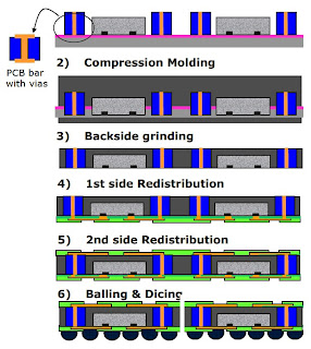
The process flow for the latter is shown below. The chips and the PCB based bars are placed on the mold carrier and the reconstituted wafer is generated via compression molding. After reconstitution the artificial wafer is ground down to make the via bar accessible for the connection with a redistribution layer. It consists of a dielectric on bottom side, redistribution layer and solder stop on top and bottom side.

Hope to see many of you at next weeks RTI 3D-ASIP conference in Burlingame CA (link)


For all the latest on 3D IC Integration and Advanced Packaging stay linked to Insights From the Leading Edge, IFTLE…………………


Saturday, November 27, 2010

IFTLE 25 IMAPS Part 2 Advanced Packaging

IBM Going Fab Lite ??

Peter Clarke of EE Times is reporting that “ … IBM appears set to gradually back away from semiconductor manufacturing and to rely for its leading-edge silicon on Samsung and GlobalFoundries as foundry suppliers (link). If you are a reader of IFTLE you already knew that [ see IFTLE 8 "3D Infrastructure Announcements and Rumors”, July 2010]

“… IBM is gradually allowing itself to exit from leading-edge manufacturing at high volume. IBM appears to have joined the broad class of semiconductor companies that will never build a major wafer fab again” reports Clarke. Interestingly the last time that IBM was close to the global top 10 was in 204 when they ranked 11th.

Several Govt. types were shocked when I shared this rumor a few months ago. Clearly they shouldn’t have been. It appears that such business decisions will take what remains of IBM manufacturing prowess the way of Bell Labs, DEC and many of the other early giants in our USA microelectronics industry..

Advanced Packaging at IMAPS National


IBM Injection Molded Solder


IMS is a variation of C4NP for solder deposition on fine-pitch laminates.
The presentation on this technology is examined in detail in the ElectroIQ advanced packaging section by the presenter Jae-Woong Nah [link]: 

RTI Int

Alan Huffman of RTI Int presented an overview of the evolution, status and possible future for bumping /WLP which I co-authored. RTI, as you know, purchased the Microelectronics Center of NC (MCNC) ~ 4 years ago. MCNC spun off Unitive which is now owned by Amkor but “back in the day” bumping pioneers such as Iwona Turlik, Dan Mis, Glenn Rinne, Paul MaGill, Phil Deane, CJ Berry, Ted Tessier, Boyd Rogers and many others developed a plated bump process that is still used globally today. In fact the joint industry standard on “implementation of flip chip and chip scale technology” put out in 1996 by EIA/IPC/JEDEC/SEMATECH/MCNC was put together at a meeting on the MCNC campus.


Historically flip chip (or C4 as IBM called it) had been around since the 1960s but things took off commercially in 1992 after Tsukada of IBM Japan announced that they had discovered that the use of underfill allowed reliable joints directly to PCBs (i.e chip-on-board). After the commercial use of flip chip in the Motorola StarTac cell phone in 1996 the commercial use of flip chip in consumer products exploded.


It is clear today that flip chip and WLP are evolving into copper pillar bump (lower electrical resistance and inductance; lower thermal resistance; better resistance to electromigration; reduced pitch) and WL fan-out packaging (allows more IO at same pitch). A complete description of Huffmans presentation is given in a podcast interview with SST Editor Debra Vogler which can be accessed here [link].

Micron
Micron's presentation on the next generation of PoP (package on package) indicated that there would be a required reduction in Z height of the top memory package. This in turn will require reducing die thickness and reducing the mold cap thickness.


While transfer molding is the standard mold method used in the semiconductor industry, this method has limitations when it comes to very low mold cap clearance. Issues include mold voids, bond wire sweep, and filler segregation.


Compression molding has been introduced in fan-out WLP for full wafer molding. Micron now reports that compression molding of PoP top memory packages is the most suitable molding method for structures with reduced mold cap thickness.


A key parameter for PoP packages is the warpage during reflow. Shadow Moiré was used for measuring package warpage. The study found that compression molding and transfer molding yielded equivalent package warpage when using the granular forms of mold compounds. For top PoP packages that tend to have thin mold caps, Micron reports that it is necessary to choose a mold compound with lower coefficient of thermal expansion CTE1 (below Tg) and CTE2 (above Tg) and lower cure shrinkage.


Finite element simulations indicated that the coplanarity, as well as warpage of small size packages (12mm x 12mm and below), could be controlled to under 100 μm.


NEPES


We have recently reported on NEPES licensing of the Freeescale RCP (redistributed chip package) technology for fan out packaging [ see IFTLE 2, “Advanced Packaging at the 2010 Las Vegas ECTC”, June 2010].


At the IMAPS National meeting NEPES took another major step in advanced packaging when they revealed the details of their silicon module (SiP) program silicon module with Cu filled TSV and IPD (integrated passive device) LPF (Low band pass filter) integrated at the surface of silicon interposer as shown below.
The 7 mm x 7 mm Si interposer is 200 um thick. The entire package is limited to < .8 mm thickness. The spiral inductor is formed in the backside RDL layers from 8 um ED copper in low K polymer. MIM capacitors are fabricate by Al/SiO2 front end TF (thin film) processes and Cu/polymer back end processes.
The LPF shown below is fabricated from two inductors of 2.508nH, one inductor of 5.24nH and two capacitors of 1.641pF fabricated by front-end Al/SiO2.

For all the latest in 3D IC integration and advanced packaging stay linked to IFTLE………….


Saturday, November 20, 2010

IFTLE 24 IMAPS National Summary Part 1 - 3D Highlights

The IMAPS USA annual or “National”, as it is known, was held in Raleigh a few weeks ago. Rajen Chanchani of Sandia National Labs took over the helm as IMAPS President during this meeting with long time industry stalwart Voya Markovich next in line. Rajen’s name should be familiar to all packaging practitioners since he was part of the team that developed the Sandia mini BGA back in 1997 [see “Mini Ball Grid Aray Assembly on MCM-L Boards”, ECTC 1997] which WLP historians like Peter Elenius and yours truly credit as the first WLP structure. Voya, all of you know for his decades long development of high density PWB solutions such as “film redistribution layer technology” at IBM and subsequently Endicott Interconnect . The photo below shows the assemblage of past IMAPS presidents that were at the Raleigh meeting.
Meeting General Chair was Dave Seeger who at the time he signed up was on loan to SRC here in the Research Triangle, but since has moved back to IBM in NY. Technical Chair was Sara Paisner from Lord which is headquartered here in the RTP area.


This years meeting had a significant 3D focus with several professional development courses and 5 sessions which included a panel session on “Roadmaps, Technical and Business Progress” We’ll first take a look at 3D and in the next blog look at other topics in in advanced packaging.


3D IC Panel session


The 3D panel session was headed up by RPI Professor James Lu, panelists are shown below:
IMAPS 3D Panel: Phil Garrou (Microelecttronic Consultants of NC); Nick Sillon ( Group Manager, CEA Leti); Klaus Hummler ( Sr Principal Engineer, Sematech); Urmi Ray ( Sr staff engineer, Qualcomm); James Lu (Professor RPI); Rozalia Beica (Program Director, EMC3D); Dorota Temple ( Program Director, RTI)


When asked about the 3D commercial timeline I commented that roadmaps of many companies (TSMC, UMC, Elpida, ASE etc.) now appeared in sinc and all point towards commercialization in the 2011-2012 timeframe. Ray commented that Qualcomm, a very public supporter of 3D IC technology , sees “two years out (2012)” as “about right”. Hummler was a little more hesitant about timing indicating that “…Nokia is pointing towards product introduction in 2013 but we believe this will be a stretch”. Beica indicated that 15 3D lines were going in place across the world (I assume this included commercial, university and institute lines)


When asked about standards, Ray, herself involved in several standards initiatives, pleaded for more work on standards “now”. Hummler commented that for fables companies standards are a “matter of survival” .


When questioned on the role of consortia and institutes, Sillon responded that “…the role of consortia is to show demonstrators of what can be done with 3D” .


Temple reminded the audience that 3D allows “.. separating digital from analog layers which results in lower power product developments” She also pointed out that we may need what she called “Second generation OSATS” which would be skilled in “..processing not usually done by the OSATS today”.


Sematech


As we have noted in the past Sematech’s role in the 3D IC infrastructure is to">drive convergence of the materials/equipment solutions by:
– creating roadmaps and standards
– working with others including Member Companies to drive convergence
– industry consensus building through workshops and forums


Klaus Hummler, who has recently moved to the Sematech Interconnect program from siXis, discussed their technical focus area namely “Via-middle” ( TSV’s formed after FEOL and before BEOL) with the following attributes:


• TSV before 3D stacking
• Wafer thinning before 3D stacking
• Back-to-face bonding
• Die to wafer bonding
• TSV diameter 5 μm
• TSV pitch 10-50um
• 20-50 μm TSV depth


Long time readers will note that this is exactly where IFTLE (and PFTLE) has been pointing you for the past 3 years.


EMC-3D / Applied


The name Rozalia Beica has become synonymous with 3D IC in the past few years. Rozalia has been one of the “faces” of the EMC3D consortium [ see PFTLE 47, “3D IC Questions and Answers from the EMC-3D Consortium” After the acquisition of Semitool by Applied Rozalia rejoined the Semitool business unit of Applied Materials working in their 3D program. Processes supported by EMC3D are shown below:


Applied has put together a lineup of tools to address TSV fabrication as shown below (sorry for the small print). Beica reports that Applied, at their Mayden Development center 3D line have  run more than 50 integrated demos.


Beica reported that their newer via fill processes show a 50% reduction in overburden and significantly purer copper which results in significantly less Cu extrusion (Cu pumping) and micro voiding.
Paul Enquist, CTO of Ziptronix reports that their direct bond oxide technology catching on with fabricators of backside illuminated CMOS image sensors. Enquist also shared the first released cross sections of a 10 µm pitch, 463,000 connection daisy chain built with the Ziptronix DBI process with Cu filled TSV fully protected by barrier layers (below). Enquist reported a 99.999% yield on such structures.


John Lannon, Sr engineer at RTI Int described the RTI bonding process developments. He warned the audience of electrical failures during reliability testing of 3D test vehicles bonded with Cu/Sn/Cu intermetallics, “…the yield goes to zero after 96 hours standard autoclave testing” Lannon added “ …standard epoxy underfills do not seem to solve the problem, but we have found a silicon underfill that allows device survival through the autoclave testing. More work is needed to completely understand this issue and all potential solutions“ An interesting dialog occurred during the question and answer period of Lannons presentation. An unknown questioner from the back of the room stated that Cu/Sn/Cu bonding used by so many of today’s 3D IC practitioners was nothing more than copper pillar bonding and that (paraphrasing) “…copper pillar bonding is patented by APS and anyone practicing this technology must be licensed by APS”. APS is of course Avanpack in Singapore and indeed I am aware that Amkor, Unisem and Flip Chip Inc have taken out such licenses. I do not support or reject the questioners statement without further study (yes – I do serve as an expert witness !) but I certainly do bring it to your attention.


Rhett Davis, Professor of EE at NC State showed much od the work that he and fellow Professor Paul Franzon have been doing in the 3D area. 3D specific designs were shown that achieved 65% power reduction and an 800% increase in memory bandwidth.


Jeremy McCutcheon of Brewer Science reviewed their Zonebond process (link) showing the audience significant details on the carrier removal step once the wafer is laminated to a film frame. McCutcheon warns that “… solvent strip on film frame an issue since some solvents attack the glue on the film frame. This step must be done properly”


Between now and the end of the year IFTLE will be looking at:


- Napa KGD conference
- IEEE ESTC Conf
- IEEE 3D Test workshop
- IEDM

- RTI 3D ASIP Conf
...as well as any and all announcements and rumors that you need to be aware of.


RTI ASIP

The RTI ASIP Conference (3-D Architectures for Semiconductor Integration and Packaging) will be held in Burlingame CA on Dec 8-10. 3-D ASIP is focused on technology advancements, business issues and infrastructure development. Among the many invited speakers are Erik Volkernik CTO of Verigy, Subramanian Iyer of IBM, Doug Yu of TSMC, Ho-Ming Tong of ASE, Bob Patti of Tezzaron, Arif Rahman of Xilinx, Marc Scannell of Leti, Bob Lanzone of Amkor and many, many other industry experts. Hope to see you there.


For all the latest in 3D IC and advanced packaging stay linked to IFTLE………………………….


Sunday, November 7, 2010

IFTLE 23 Xilinx 28 nm Multidie FPGA, Copper Pillar Advances at Amkor and Intel Looking at Foundry Options

Took a little time off to have Halloween with grandaughters Hannah and Madeline in Houston. If you’re a kid in America what a great holiday Halloween is. Basically, strangers give you candy for dressing up and pretending to be someone or something your not. Hummm…come to think of it, this is a bit like politics where politicians pretend to be something their usually not (honorable, honest, concerned ) when really all their after is the candy. When it comes to trick-or-treat we are usually the ones who are tricked. Well that’s a discussion for another day. Hannah (6) and Madeline (2) certainly had a great time as you can see below.

Xilinx 28 nm FPGA will use Si Interposer


The true 3D aficionado has been waiting for the first true commercial product announcement. We already have face to face stacking without TSV (chip-on-chip in the Sony Playstation and many other products) and TSV being used for 1 layer image sensors (nearly all of todays CMOS image sensor manufacturers) but when will we see a true 3D design which will contain (a) TSV, (b) stacking and (c) thinning ?


We were teased this past week with headlines such as “Xilinx Stacked Silicon Interconnect Extends FPGA Technology to Deliver 'More than Moore' Density, Bandwidth and Power Efficiency”. I must acknowledge that it does not directly say anything about 3D, but there certainly was a lot of buzz in the industry since the packages make use of TSV interposers.


We have seen a lot of structures recently that use the silicon interposer to mate die to the top and bottom of the interposer (i.e the Renesas SMAFTI) . Last week Xilinx announced a single layer, multi chip silicon interposer for its 28nm 7 series FPGAs. These FPGAs reportedly extend the range of applications programmable logic can address by offering up to 2 million logic cells for high levels of computational performance and high bandwidth.


The 28nm Virtex-7 LX2000Tmulti die FPGA will provide more than 3.5X the logic for capacity of the largest current-generation Xilinx 40nm FPGA with serial transceivers and 2.8X the logic capacity of the largest competing 28nm FPGA with serial transceivers.


Within the Xilinx stacked silicon interconnect structure, data flows between a set of adjacent FPGA die across more than 10,000 routing connections. Compared with having to use standard I/O connections to integrate two FPGAs together on a circuit board, stacked silicon interconnect technology provides over 100X the die-to-die connectivity bandwidth per watt, at one-fifth the latency, without consuming any high-speed serial or parallel I/O resources. By having die sit adjacent to each other and interfaced to the ball-grid-array, Xilinx can avoid any thermal and/or design issues that would be introduced had a pure 3D IC vertical die-stacking approach been taken. This will reduce power, and improve performance compared to a multi-FPGA approach


Xilinx reports that they have been working with TSMC and their assembly house Amkor. The device is made possible by Amkors micro-bump assembly, FPGA architectural innovations from Xilinx, and advanced technology from TSMC. The new products deliver lower levels of power consumption, system cost and circuit board complexity compared to using multiple FPGAs, each in their own package, for the same application.


By using TSV silicon interposer to implement their stacked silicon interconnect approach, Xilinx reported that they “ reduced the risk involved with thermal and design issues of full 3D IC stacking” This probably means that full 3D just is not ready yet and we will be seeing more ”Xilinx like” designs in the near future before we see full 3D in a few years from now.

According to Xilinx, Initial devices will be available in H2 2011.


For more technical information including white papers, visit the Xilinx web page at: http://www.xilinx.com/stackedsilicon.


Amkor /TI Copper Pillar Technology


The week before Semicon West Amkor and TI announced that they had qualified and begun production of the industry's first fine pitch copper pillar flip chip packages – shrinking bump pitch up to 300 percent compared to current solder bump flip chip technology [link]


Very little follow up was available because of the exclusivity TI was given as part of the joint development program. The publically available data left me once again asking “Where’s the Beef” [ see IFTLE 3 "…on finding the beef and finally addressing 3D IC"]


I was personally told that full technical details are being withheld till the next ECTC conference [ June 2011].


Last week Amkor did release come details on their technology. For all the available information on this technology see the amkor website here (AMKOR) .Design rules are shown below.


The Weibul plot shown below shows an improvement in life for Copper Cu pillar over SnAg bump for the same current / temperature condition and similar bump / UBM geometry. No failure was observed in Cu Pillar Bump even after 8000 hours of testing at the same condition.
Fellow blogger Dick James has done some reverse engineering which can be found here (link).[added 11/09/2010]

Intel Becoming a Foundry ??

Intel has agreed to manufacture a specialized microprocessor design for Achronix Semiconductor at its most advanced factory [link]. While the production use less than 1% of Intels production capacity, it certainly is a departure from their normal business model and may point to their experimenting in the foundry business to keep such options open for the future. While Intel is brushing this off as non important, I would kep an eye out for similar developments.

For all the latest in 3D IC and advanced packaging stay linked to Insights From the Leading Edge….